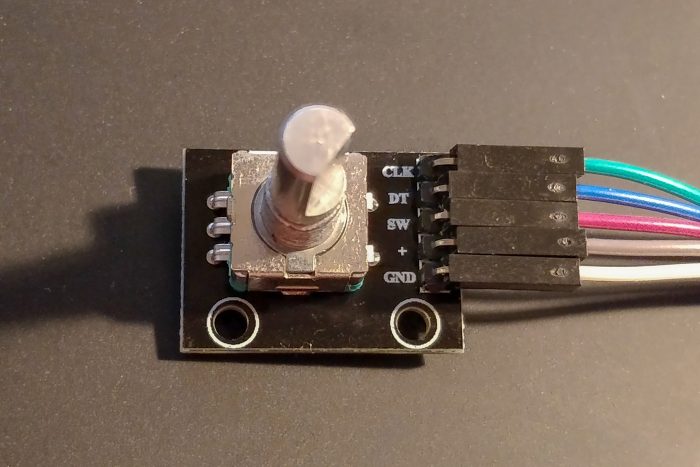
For a project I with a Raspberry Pi (Zero W) needed a simple and easy input device to change a numerical value. So I bought some rotary encoders off Amazon.
If you search the Internet for information/tutorials on how to use a “KY-040” rotary encoder with Linux and the Raspberry Pi, you’ll find a dozen people or so who’ve done that, and written about it. Naturally, I’ll need to do that too — with a twist.
The most often referenced code to operate the KY-040 seems to be from Martin O’Hanlons Raspberry Pi and KY040 Rotary Encoder blog post, which even ended up being a python module KY040. The down side of this approach is that it’s very unreliable: The code triggers on an edge of one of the GPIO inputs and then reads the other input, all in Python code. To make this sort of work it needs long debounce times. The net result is that the code misses many turn events if the shaft is turned too fast, and sometimes gives the wrong turn direction.
I’m also not positive that Martins explanations of the signal output of the encoder is correct. Keyes KY-040 Arduino Rotary Encoder User Manual has a different explanation for the working principle, and some Arduino code. The difference is that, although the pins on the module are marked “CLK” and “DT” (for clock and data), it’s more common for rotary encoders to simply have pin “A” and pin “B”.
This matches what I’ve seen on this module: With pins A and B the most important distinction is the order in which they generate edges. If you only look for edges on one pin (“clock”) and then sample the other pin (“data”) you’ll kind-of also get information about the turns, but depending on the edge rate and sample speed it’s going to be unreliable.
It’s possible to observe both edges in Python with RPi.GPIO, but again, there’s a lot of overhead for what should be mostly real-time processing and is not fully reliable.
Good thing we’re using Linux which has device drivers for all sorts of things. Including, of course, a rotary encoder connected to GPIOs: rotary-encoder.txt (includes nice ASCII art on the operational principle).
Good thing also we’re using the Raspberry Pi, which has a matching device tree overlay (README for precompiled firmware).
(Note: If you’re compiling your own kernel, you’ll need the Raspberry Pi kernel starting with 4.9.y, CONFIG_INPUT_GPIO_ROTARY_ENCODER, and you’ll probably also want CONFIG_INPUT_EVDEV. The rpi-firmware with compiled overlays needs to be recent-ish, ~mid January 2018, for these examples to work.)
To enable/configure the rotary-encoder device tree overlay, simply put something like the following into /boot/config.txt (with the encoder connected to pins 23 and 24 on the Raspberry Pi):
# enable rotary encoder
dtoverlay=rotary-encoder,pin_a=23,pin_b=24,relative_axis=1
After a reboot you’ll have a new device in /dev/input/ for the rotary encoder. You can use the evtest tool (as in evtest /dev/input/event0) to look at the events it generates and confirm that it reacts perfectly to every turn of the encoder, without missing a movement or confusing the direction.
While you’re at it, you might also want to add the middle button as a key (mine is connected to pin 22):
dtoverlay=gpio-key,gpio=22,keycode=28,label="ENTER"
In order to make use of this in your Python programs: Use python-evdev.
# -*- encoding: utf-8 -*-
from __future__ import print_function

import evdev
import select

devices = [evdev.InputDevice(fn) for fn in evdev.list_devices()]
devices = {dev.fd: dev for dev in devices}

value = 1
print("Value: {0}".format(value))

done = False
while not done:
  r, w, x = select.select(devices, [], [])
  for fd in r:
    for event in devices[fd].read():
      event = evdev.util.categorize(event)
      if isinstance(event, evdev.events.RelEvent):
        value = value + event.event.value
        print("Value: {0}".format(value))
      elif isinstance(event, evdev.events.KeyEvent):
        if event.keycode == "KEY_ENTER" and event.keystate == event.key_up:
          done = True
          break
